

Hi all, this is a short report on what I have been doing in the last few months (up to dec/2013).
I have been looking at the 128-electrode datasets that Claudia uploaded to ~/Dropbox/eeg_sinal_ghislain/ a while ago (S13.raw and S14.raw). I have extracted the runs as separate files, filtered and plotted them.
I have some observations and questions about the data.
The trigger pulses (in channels HB, HS, QB, QS, and fix1) last only one frame, correct? (I ask because in the 20-electrode datasets each trigger pulse spanned several frames.)
The CZ channel is always exactly zero, correct?
I understand that the first 128 data channels are the potential differences (in microvolts) between the 128 numbered electrodes and the reference electrode, correct?
The reference electrode is the one labeled VREF in the electrode diagram (surrounded by C7 C106 C80 C55 C31), correct? It is not the unlabeled white disk a little further back (surrounded by C55 C79 C78 C62 C61 C54)?
For each experimental run, I extracted a segment from the original dataset (S13.raw or S14.raw), exactly 7 seconds long, spanning a fixation phase and the following stimulus phase, plus some extra frames at both ends. The length of the two phases varies somewhat, but the extracted files have the fixation-to-stimulus transition always at the same moment, exactly 3.5 seconds after the start of the file.
In the original files, the potential of each electrode includes a very large and seemingly arbitrary DC offset (up to 20 mV = 20.000 µV), mostly constant but different for each electrode. This offset seems to vary (gradually or abruptly?) along the session, and from session to session.
Therefore, when extracting the individual runs I had to compute some 'mean' potential of each electrode in each run and subtract it from its data values, just to be able to plot them. Apart from this mean shift, no other processing was done on the raw runs.
The figures below show three typical extracted runs, with the constant offsets subtracted fromeach electrode. The notation s013_r00209 means subject 13, block 2, run 9, etc.
For each run, the leftmost plot shows all 128 channels as a function of time (seconds) since the
start of the file. Next to it are two plots of the power spectra of
those channels, one from 0 to 35 Hz, the other from 0 ro 250 Hz
(the Nyquist frequency limit). Note that the vertical scale is logarithmic.


What is the physical explanation of those large constant offsets, and their drifts within each session? Can they be eliminated at the source?
Note that 1% of 5.000 µV is 50 µV. Thus, even relatively small oscillations in these offsets, say 1% or less and lasting less than a second, will be confused with significant EEG signals.
Besides these large offsets, there is an enourmous amount of
60 Hz power line noise and its harmonics (over ±200 µV amplitude in some channels, over ±50 µV in
several of them).
The power line noise can and will be be removed by software filtering, which is
supposed to discard everything above 40 Hz (see below). However, I am
worried that this noise may still contaminate the filtered data.
If you recall, in the 20-electrode sets we obsered a significant 30 Hz component that we conjectured to be a sub-harmonic of the 60 Hz noise (or interference from a computer fan motor running 1800 rpm). Any lower sub-harmonics of the power line noise (say 20, 15, or 10 Hz) would fall into the range of frequencies that are to be preserved by the software filtering step.
Since data above 40 Hz is going to be discarded anyway, could it be possible to apply a 40 Hz hardware lowpass filter to the signals before sampling and A/D conversion? (I understood that the 20-electrode equipment had a notch filter that removed the 60 Hz noise specifically, but passed the 30 and 90 Hz harmonics.)
Hardware pre-filtering would allow the use of lower sampling rates (say, 200 or 150 Hz instead of 500 Hz); and that in turn may improve the accuracy of the sampled values.
Another way to reduce the power line noise would be to place the subject inside a shielding cage, e.g. of chickenwire mesh. Perhaps the display's power source (or its power cable) is a source of the 60 Hz noise?
In many runs there is also a sharp peak in the spectrum around 80-85 Hz. Could this be due to the "microtremors" of the eyes? According to some papers I found, they are small involutary rotations of the eyeball (by about 1 degree) that allow the eye-brain system to compensate for the blind spots caused by blood vessels over the retina. According to those papers, the frequency of these microtremors is fairly constant from person to person, about 84 Hz.
After extracting the runs, I passed them through a Fourier-based bandpass filter.
For the low-pass and band-pass stages, I tried the Butterworth filters used in the 20-electrode tests, but I found that they produced substantial "ringing" whenever the input had a spike or a sharp step.
I therefore used Gaussian filters instead. Their transitions from "pass" to "kill" are more gradual but they are free of ringing.
The following plots compare the effects of both filters. The top figure shows some synthetic signals (an impulse, some bell-shaped pulses, a square pulse and a chirp). The next two figures show the output of the Gaussian and Butterworth filters, respectively, on those signals.


Fourier-based filters assume that the input signal is periodic. This is not a viable assumption when the input includes substantial variations whose period is longer than the signal sample, such as random drift. For the Fourier filter, those long-period variations create a discontinuity in the signal at the end of each period, which gives rise to spurious artifacts near both ends when it is smoothed out by the filter.
Unfortunately, such long-period drifting is conspicuous in many raw runs, as noted above. To reduce the artifacts, I fitted a cubic polynomial (by a robust variant of least squares) to each electrode signal in each run, and subtracted it from the signal, before applying the Gaussian filter.
Here are some samples of filtered runs, and their power spectra:
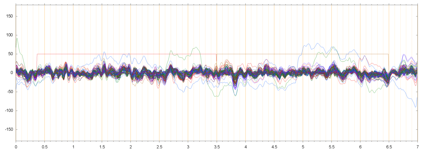

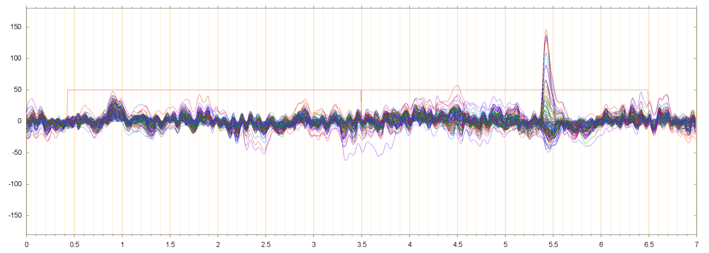
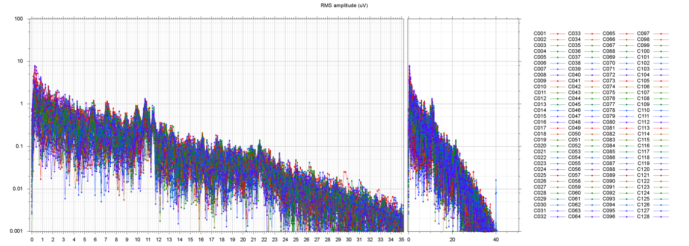
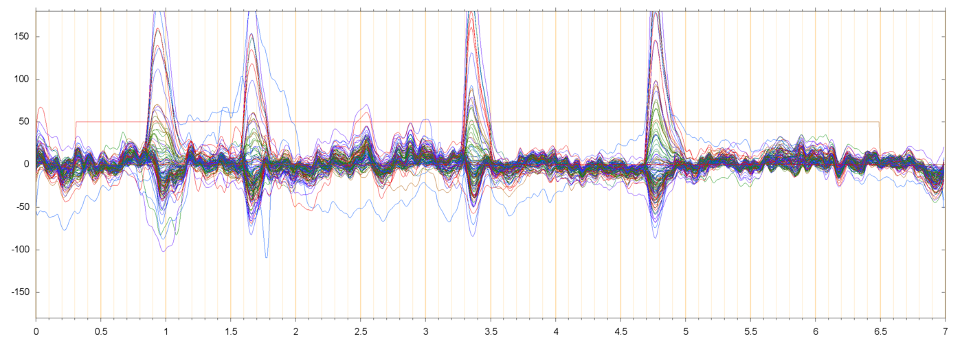
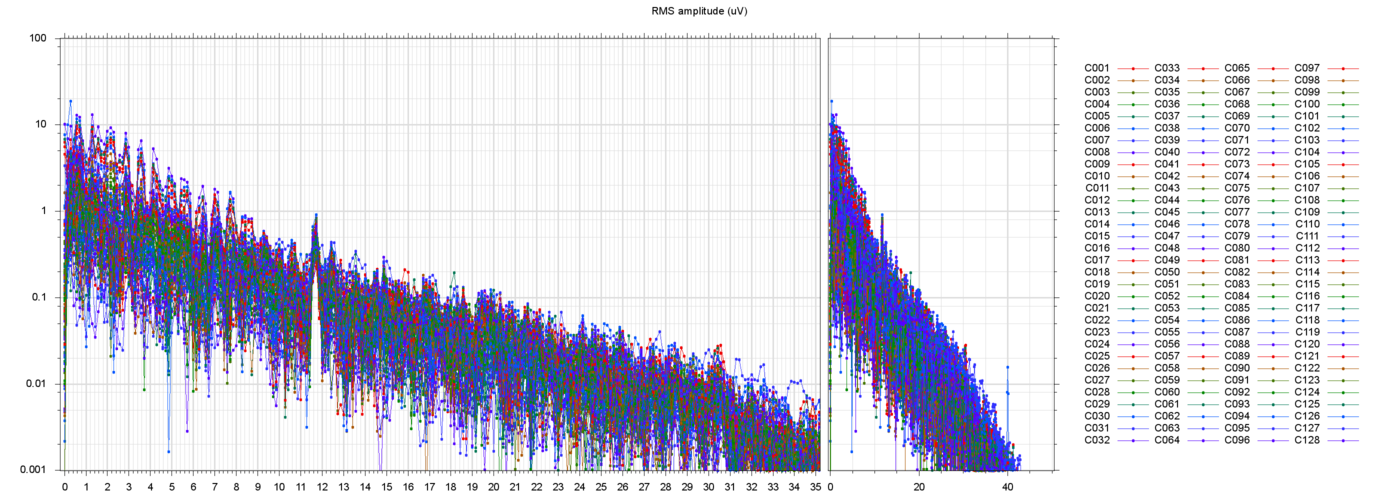
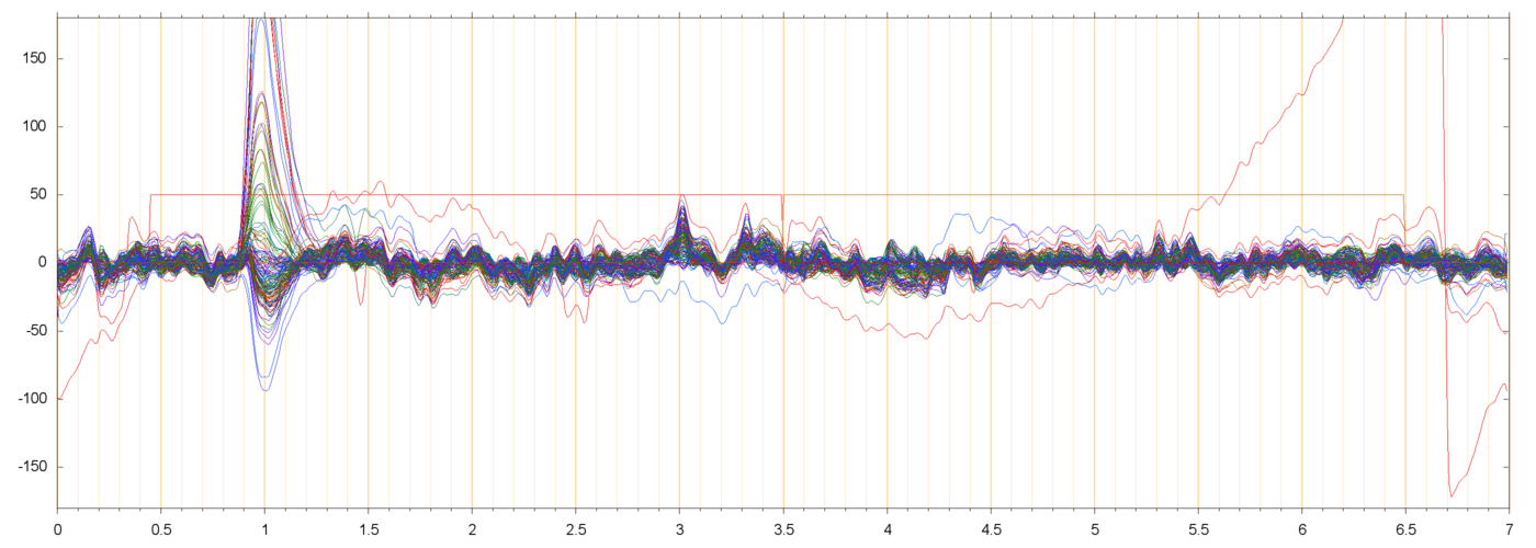
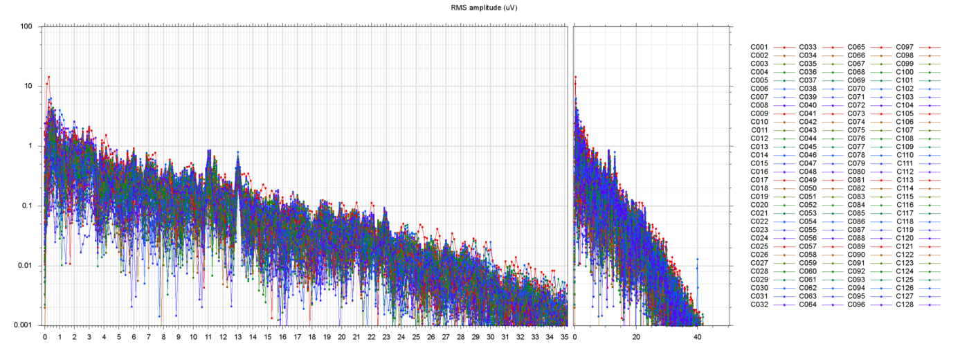
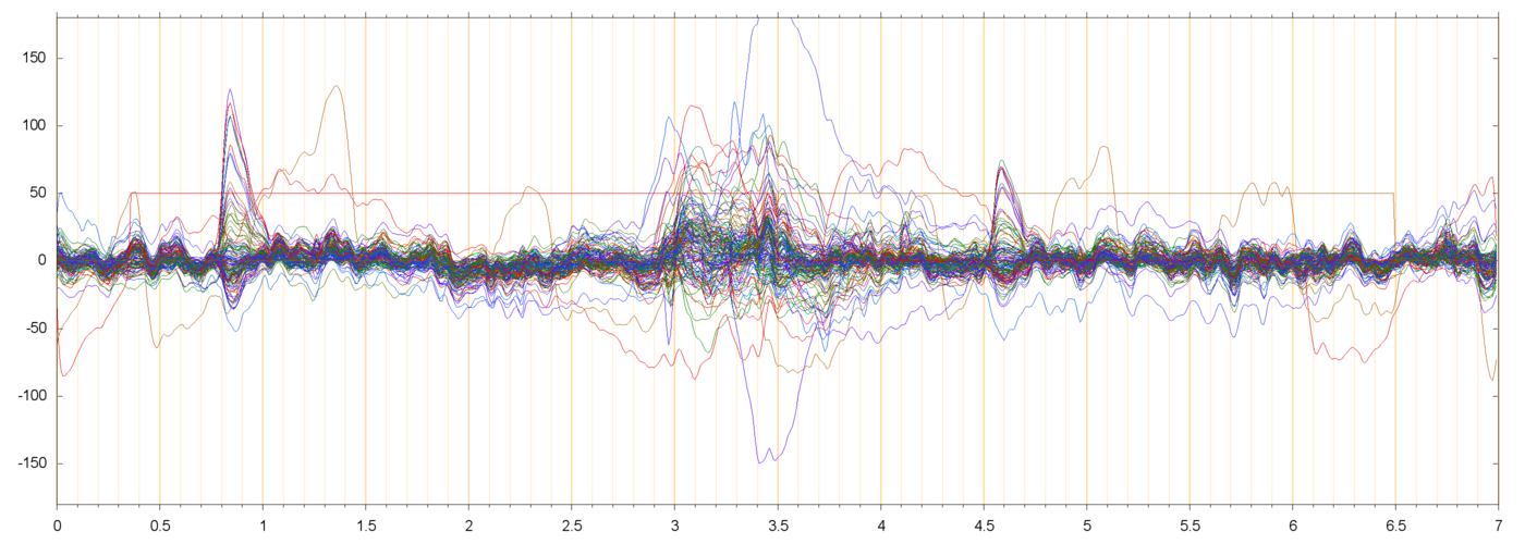
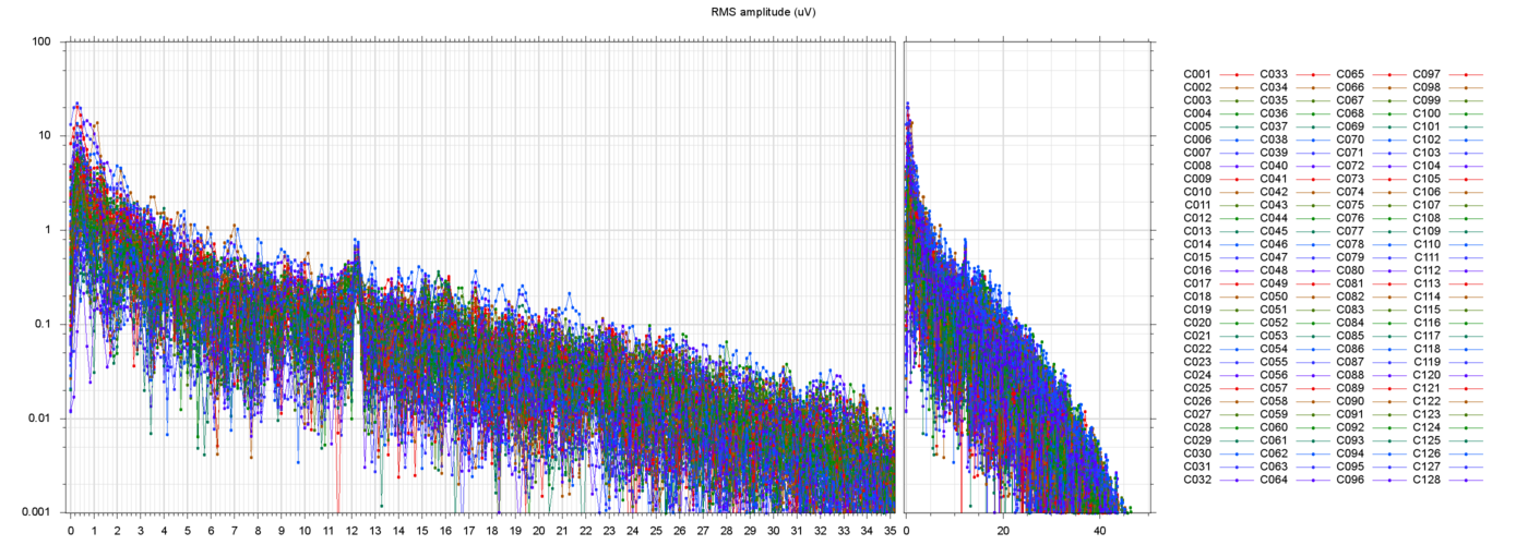
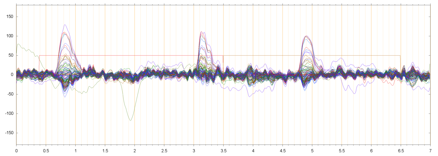

These plots show that the filtering succeeded in removing most of the drift and power-line noise, leaving a set of fairly cohrent signals.
In almost every run there are a couple of electrodes that seem to be drifting randomly, by 50 µV or more, quite independently of their neighbors. Since such independence is not physically possible, those channels are probably garbage. I suppose that they should be removed from the data, but I have not done so.
I am assuming that the large pulses seen in these plots (usually peaking at 50 to 200 µV, and lasting from 0.3 to 0.5 seconds) are neuro-muscular signals due to the subject blinking. These are discussed in more detail below.
In all runs that I have checked, there is a noticeable bump in the spectrum around 10 or 11 Hz. This is discussed further down, too.
In a few runs there were very large oscillations of the electrode signals, apparently random and independent from electrode to electrode, as in the folowing example:
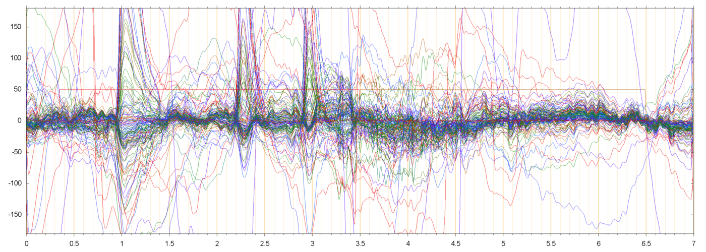
Such "crazy" runs often occur as the first run of a new block. I presume that they are due to the subject shifting the head to focus on the fixation cross after a "rest" period, is that so?
Bad news: almost every extracted run contains one or more blink pulses, and most of them may have to be discarded. Good news: the blink pulses have a fairly simple, single-component model. Bad news: there may be significant "sub-blink" muscular signals even when there seem to be no blink pulses:
Presumably blinks are not a problem unless they occur in the "important" part of the run. I arbitrarily assumed the "important" part to be the last 1 second of the fixation phase and the entire 3 seconds of the stimulus phase (4 seconds in total). Even so, I found that most runs would have to be discarded: only 91 runs of subject 013 (36%) and 16 runs of subject 14 (6%) were free of blinks or other accidents in the "important" interval.
Perhaps not surprisingly, I found that blinks are not uniformly distributed in time. The following histograms shows the distribution of the blink's position as a function of the time since the start of the extracted run file, for the two subjects:
| s013_blinks_hist | s014_blinks_hist | |
 |
 |
Recall that the fixation-to-stimulus transition occurs at precisely at t=3.5 seconds after the start of each run file. The fixation phase begins around t=0.5 seconds (sometimes a bit earlier) and the stimulus phase ends at t=6.5, usually with the start of another fixation phase.
From these plots, it seems that both subjects are much more likely to blink around t=1.0, that is, about 0.5 seconds after the start of the fixation phase. (The timing of those blinks may be even more regular than it seems in the plot, since the peak is somewhat broadened by the variation in the starting time of the fixation phase.)
Conversely, blinking seems to be suppressed during the first 0.5 seconds of the stimulus phase.
Within the stimulus phase, subject 014 is more likely to blink about 1 second into it, whereas subject 013 shows no preference after the initial suppression period.
The blink pulses vary substantially from subject to subject (or session to session), presumably due to changes in the anatomy, to different "blinking styles" (which muscles are activated in the blink), or simply to different placements of the electrodes.
On the other hand, blink pulses are remarkably similar within the same subject and session. While there is some variation in the duration and amplitude of the blinks, all electrode potentials rise and fall together, in fixed proportions, throughout the blink pulse. In other words, there is a single voltage distribution over the skull that changes only by a common time-varying factor.
To find that pattern I extracted all blink pulses from each session, and ran a principal component analysis on them. The dominant component (the one with largest intensity), for each subject, is shown graphically below:
| s013_blinks_P000_eig_b2_f000000 | s014_blinks_P000_eig_b2_f000000 | |
 |
 |
In these plots, as in my previous animations, lighter and warmer tones are supposed to indicate positive voltages, darker and bluer tones are negative. However, the two patterns above had their polarity accidentally reversed by the PCA algorithm. Thus, during a blink pulse the frontal region becomes positive while the rest of the scalp becomes negative. The latter includes the temporal(?) electrodes (C125 and C128) and the maxilar(?) ones (C126 and C127).
These patterns have surprising bilateral symmetry, and their similarity too is surprsing considering the apparent difference between the plotted pulses of the two subjects.
Another conspicuous feature in the time-base plots of the filtered runs is an irregular oscillation with about 10 cycles per second, affecting almost all channels in synchrony. This oascillation clearly matches the 10 Hz bump in the power spectra, whose width indicates that the frequency varies somewhat along a run.
This 10 Hz oscillation too appears to be due to a single voltage pattern on the skull. That is, all electrode potentials change together, in fixed proportions, by a time-varying factor.
To identify this pattern, I performed a PCA of the blink-free "important" segments of all runs, for each subject. Namely, I extracted from each run that had no "crazy" behavior the last 1 second of the fixation phase and the 3 seconds of the stimuls phase, and discarded those that included any blink pulses (as idenfied previously by visual inspectio, see above). The concatenation of all those segments was then subjected to PCA.
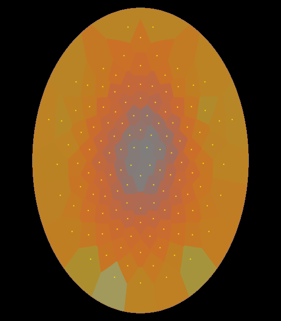
The 10 Hz voltage pattern showed up as the first principal component in both subjects, shown below:
| s013_nonblinks_P000_eig_b2_f000000 | s014_nonblinks_P000_eig_b2_f000000 | |
 |
 |
These diagrams show that the 10 Hz oscillation increases as one moves away from the reference electrode, rather uniformly in every direction. It is as if the source of that pulsation was not inside the skull, nor somewhere on the scalp or face, but in the neck or lower.
The pattern of subject 13 is stronger on the back of the head, suggesting that neck muscles are involved.
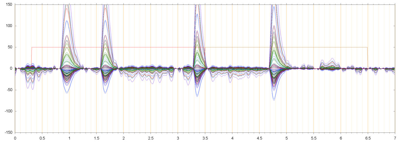
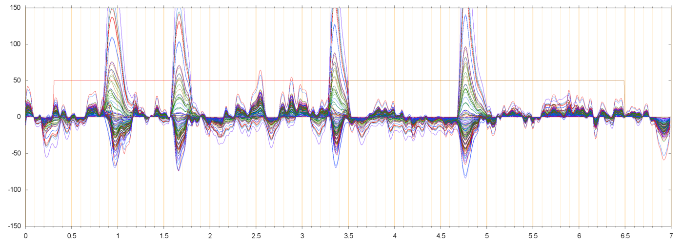
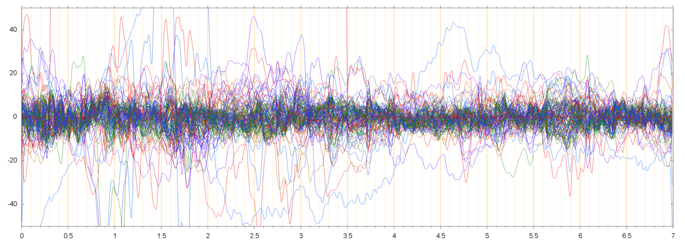
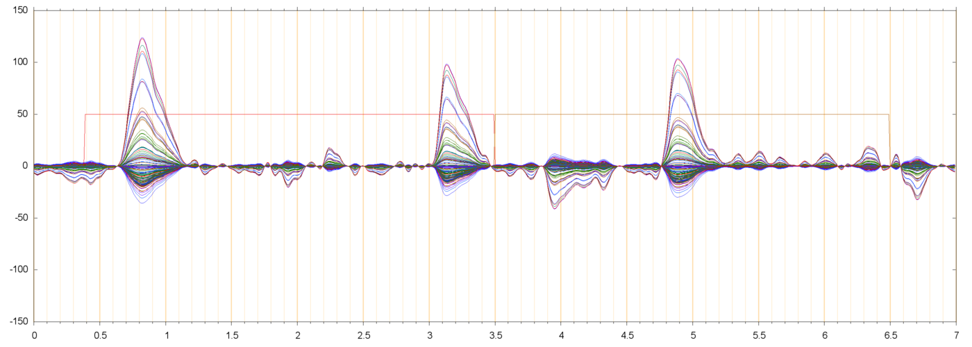
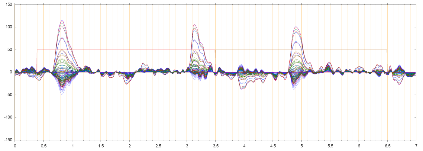
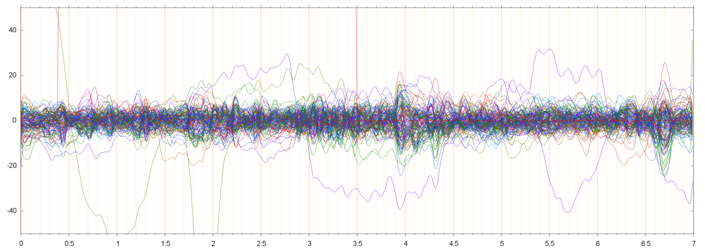
I tried to separate the filtered runs into a combination of the two components identified above --- the blink pattern (BL0) and the general 10 Hz oscillation pattern (H10) --- and a residue (RES) that is orthogonal to both patterns. See the figures below.
| s013_r00229 | ||
 |
| s013_r00229_BL0 | ||
 |
 |
| s013_r00229_H10 | ||
 |
 |
| s013_r00229_BLH | ||
 |
| s013_r00229_RES | ||
 |
| s014_r00425 | ||
 |
| s014_r00425_BL0 | ||
 |
 |
| s014_r00425_H10 | ||
 |
 |
| s014_r00425_BLH | ||
 |
| s014_r00425_RES | ||
 |
The negative parts of the extracted blink signal (such as in s013_r00229_BL0 between t=2.0 and t=3.0) are not sigificant. The principal component analysis is formulated in such a way that every extracted component has necessarily zero mean value in every electrode. Therefore, the "positive" pulses that correspond to blinks must be compensated by a spurious "negative" signal between blinks. I will try to reformulate the analysis to avoid these artifacts.
Note that the scale of the residual plots (s013_r00229_RES, s014_r00425_RES) is different from the other plots. For most electrodes, the amplitude of the residual signal is about 10 µV.
In the residual plots one can still see events that affect many electrodes together simultaneously. For example, in s014_r00425_RES these events are visible around t=0.5,t=2.0, t=4.0, and several other places. These events presumably are the next significant PCA elements; to be checked.
Last edited on 2013-12-07 16:14:35 by stolfilocal