Next: Modularize Architectural Variation Points Up: Design of Component-Based Software Previous: Initial SPL architecture Contents
After mapping features to components, it is important to specify component interfaces. The inputs of this activity are initial SPL architecture (see Figure 10) and use case specifications (Section 5.4). The first step is to identify both crosscutting and base-level interfaces. This identification is based on the relations that have been copied from the transformed feature model and from the transformed spect-feature view to the initial SPL architecture. These relations can be of the following types: uses, alters, contradicts, crosscuts, or preceded-by. The first three relations can become base-level provided and required interfaces. Crosscuts relations can become crosscutting provided and required interfaces and Preceded-by relations are realized within crosscutting connectors and they are further detailed in Section 5.7. An example of how base-level interfaces are identified: SupportSer vices component uses ComplaintMgr component, so this relation becomes a base-level required interface of SupportServices component and a base-level provided interface of the ComplaintMgr component. Crosscutting interfaces are similarly identified, for instance, Distribution component crosscuts ComplaintMgr component, thus this relation can become a crosscutting provided interface of Distribution and a crosscutting required interface of ComplaintMgr component. In some cases, relations between features do not become new provided and required interfaces, because an existing interface might be reused.
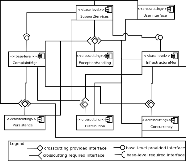
After identifying base-level and crosscutting interfaces, their operations are identified based on use case scenarios. If a use case step is considered system's responsibility, then it can be represented as an interface operation. For instance, the Specify complaint use case has several steps that might be represented as interface operations of the ComplaintMgr component. These operations can be later collapsed or split depending on their interaction. For example, if there are several consecutive use case steps that are system's responsibility, these can be collapsed into a single operation. This approach for identifying interface operations is based on an activity of a component-based development process called UML Components [41]. Our solution adapts it to also handle the specification of crosscutting interfaces. The specification of such interfaces involves extension points and extends relations between use cases. In Figure 11, suppose that the crosscutting required interface of ComplaintMgr component is called XPIComplaint and the crosscutting provided interface of Distribution component is called AADistribution. The Specify complaint use case presented in Figure 7 has an extension point called Send data over the internet, which is extended by Provide remote access use case. This extension point can be realized by join points that are exposed by means of XPIComplaint interface. Provide remote access use case supports the specification of pointcuts and advices of the AADistribution interface.
The notation used to represent a component-based architecture with aspects shown in Figure 11 extends UML 2.4 [42] component diagram notation to represent crosscutting interfaces. The «crosscutting» and «base-level» UML stereotypes identify crosscutting and base-level architectural elements, respectively. Other notations have been proposed by the AOSD community, such as Chavez [43] and Krechetov et al. [44], and could also be used to represent the component-based SPL architecture with aspects. However, the notation used in this work fits our solution as it distinguishes crosscutting and base-level components and interfaces. Note that stereotypes are also used to represent mandatory and variable architectural elements.
Leonardo Tizzei 2013-02-18