Combinational Building Blocks
Rodolfo Azevedo
Institute of Computing, University of Campinas (UNICAMP), Brazil
rodolfo.azevedo@unicamp.br
http://www.ic.unicamp.br/~rodolfo/mo801
Goal of this class
Module 1, Class 2: multiplexers, decoders, comparators — and always_comb.
In A01 we described single gates with
assign. Today we compose those gates into standard building blocks and introducealways_comb— the construct for describing more complex combinational logic in a readable way.
At the end of this class, you should be able to:
- Implement multiplexers, decoders, and comparators in SystemVerilog using
always_combandcase. - Explain the latch inference trap and write latch-free combinational blocks with complete case coverage.
- Compose standard combinational building blocks using both structural and behavioral SystemVerilog.
- Use parameterized modules to build reusable, width-generic components.
The multiplexer (MUX)
A 2:1 MUX selects one of two data inputs based on a select signal:
| \(S\) | \(Y\) |
|---|---|
| 0 | \(D_0\) |
| 1 | \(D_1\) |
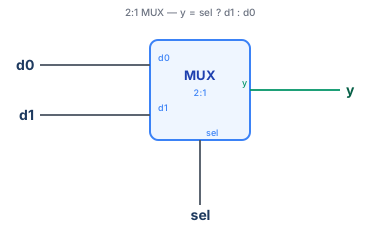
The ternary ? : operator is shorthand for a 2:1 MUX — you will see it constantly in datapath descriptions.
4:1 MUX from 2:1 MUXes
A 4:1 MUX selects among four inputs using two select bits. Build it from three 2:1 MUXes:

MUXes as universal logic
Any Boolean function of \(n\) variables can be implemented with a \(2^n\):1 MUX whose data inputs are the truth-table entries. This is exactly how LUTs (Look-Up Tables) on FPGAs work — a 6-input LUT is a 64:1 MUX.
always_comb — describing combinational logic procedurally
assign is fine for simple expressions. For more complex logic (if/else, case), use always_comb:
always_combre-evaluates whenever any signal it reads changes — exactly the semantics of combinational hardware.- Tools verify that every output is assigned on every path. A missing
defaultthat leavesyundriven on some input combination would infer a latch.
Add
defaultto everycase.
Arithmetic vs. bitwise operators
Two categories of operators; confusing them is a frequent source of bugs:
| Category | Operators | Operand(s) | Result |
|---|---|---|---|
| Bitwise | & \| ^ ~ |
Two vectors | Vector, same width — each bit independently |
| Reduction | & \| ^ (prefix) |
One vector | 1-bit result |
| Arithmetic | + - * |
Two vectors | Sum/diff (wraps on overflow) |
| Logical | && \|\| ! |
Any | 1-bit boolean |
| Comparison | == != < > |
Two values | 1-bit boolean |
Rule: use &&/|| inside if conditions and assertions; use &/| for bit manipulation of vectors. Mixing them compiles but produces wrong hardware.
The accidental latch — The most common beginner bug in SV
Fix 1 — add default:
Fix 2 — assign a default before the case (idiomatic for complex logic):
The second pattern is especially useful when most cases share the same output — you only enumerate the exceptions.
begin / end — block delimiters
In an always_comb (or any procedural block), a case arm or if branch executes one statement unless you group with begin/end:
Rules of thumb:
* The always_* block itself always uses begin/end.
* Inside case arms: add begin/end whenever the arm has more than one statement.
* When in doubt, always use begin/end — it costs nothing and avoids the classic dangling-else bug.
Decoder
An \(n\)-to-\(2^n\) decoder asserts exactly one output for each input combination:
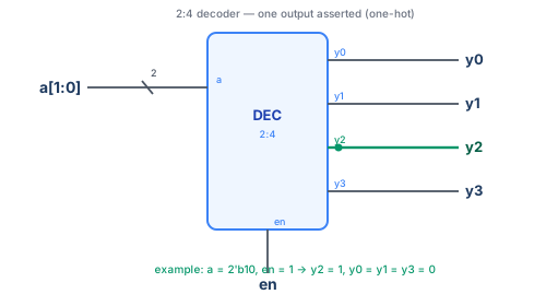
Decoders appear everywhere in this course: * Address decoding in a memory-mapped bus — select the right peripheral * Register file write-enable — enable exactly one register * Instruction decode — in Project 1's control FSM, exactly one opcode matches
A priority encoder inverts this: given multiple asserted inputs, it outputs the binary index of the highest-priority one.
Priority encoder
A priority encoder outputs the binary index of the highest-priority asserted input. Convention, lower index = higher priority:
|reqis a reduction OR — 1 if any bit is set.casezevaluates top-to-bottom; the first matching arm wins, encoding the priority order.- A priority encoder is the inverse of a decoder: decoder (index→one-hot), encoder (one-hot→index).
Where this appears in the course: the bus arbiter in Project 2 uses priority encoding to resolve simultaneous requests.
Comparator
Comparing two \(n\)-bit numbers is a standard building block for branches (BEQ, BLT in RISC-V):
- The
signedkeyword tells the tool to treat the vector as two's complement. - Without
signed,8'hFFis greater than8'h01(255 > 1 unsigned), but8'hFFis less than8'h01(−1 < 1 signed). ==produces a single-bitlogic— exactly what you need for a branch condition.
Instruction decode: a plain case
RISC-V opcode bits instr[6:0] select the instruction format — each value here is fully specified, so a plain case is all you need:
- No don't-care bits here — every opcode is matched exactly.
- Always add a
default.
casez and casex — wildcard matching
Now suppose the decoder only needs to know "is this an ALU op?" — it doesn't need to distinguish R-type (register operand) from I-type (immediate operand), and those two opcodes differ only in bit 5:
casez:?andzbits in the case items are don't-cares.casex:xbits are also don't-cares — avoid in synthesizable code, asxhas simulation-only semantics and can mask real bugs.- Prefer
casezovercasexwhen wildcard bits are needed — don't letxhide real bugs. Always add adefault.
One-hot select: a minimal bus
A one-hot select picks one of \(N\) sources based on a one-hot enable vector — the combinational core of a simple bus:
- One-hot
selmeans at most oneifbranch fires — theforloop collapses to a chain of?:. - Synthesis generates a tree of 2:1 MUXes, one per source.
- In Project 2's bus, the address decoder produces a one-hot
selvector; this MUX routes the response back to the CPU.
The for loop inside always_comb is unrolled at elaboration time — it generates \(N\) parallel if statements, not a sequential loop in hardware.
In-class exercise — combinational blocks
Exercise 1 (5 min): write a 3-to-8 decoder with enable, using always_comb and the shift pattern (8'b1 << a). Test mentally: if en=1 and a=3'd5, which output bit should be 1?
Exercise 2 (10 min): the casez below has a subtle error. Find it and fix it.
Hint: what happens when
req = 4'b0000? What does the synthesizer infer?
Exercise 3 (discussion): rewrite the priority encoder using the two-process pattern (default assignment before casez) to eliminate the latch. Which style do you prefer for readability?
Lab 3 out — decoder on the Tang Nano 9K
Goal: implement a 2-to-4 decoder where inputs are the 2 push buttons and outputs drive 4 of the 6 LEDs (active-low).
Extend for full credit: add a free-running 2-bit counter so the decoder cycles through all four outputs automatically when no button is pressed. Synthesize, load, and verify each LED lights exclusively.
Next class
Sequential Logic & SystemVerilog: flip-flops, registers, counters — and always_ff — the building blocks that add memory to circuits.