Peripheral Design: UART, Timer, GPIO
Rodolfo Azevedo
Institute of Computing, University of Campinas (UNICAMP), Brazil
rodolfo.azevedo@unicamp.br
http://www.ic.unicamp.br/~rodolfo/mo801
Goal of this class
Module 3, Class 3: implementing memory-mapped peripherals and writing their C drivers.
A peripheral is a module that sits on the bus, responds to load/store transactions, and does something useful with the outside world. Today we build three essential ones: UART (text output), timer (cycle counting and delays), and GPIO (LEDs, buttons). Together they give your processor a complete software environment.
At the end of this class, you should be able to:
- Implement a UART transmitter with baud rate generator and shift register in SystemVerilog.
- Design a memory-mapped timer peripheral with microsecond-resolution cycle counting.
- Implement GPIO for LED output and debounced button input.
- Write C drivers for each peripheral using
volatile pointer-based memory-mapped register access.
UART: asynchronous serial communication
UART sends data one bit at a time at a fixed baud rate (bits per second). A common rate: 115200 baud.
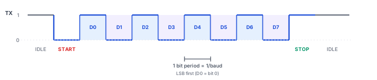
- Start bit: always 0, signals the beginning of a byte.
- Data bits: 8 bits, LSB first.
- Stop bit: always 1, returns line to idle.
- No clock line: both sides must agree on baud rate in advance. Mismatch → garbled data.
Bit period at 115200 baud: \(1 / 115200 \approx 8.68\) µs = 234 clock cycles at 27 MHz.
UART transmitter: baud generator + shift register
| module uart_tx #(
parameter CLK_FREQ = 27_000_000,
parameter BAUD_RATE = 115_200,
localparam CLKS_PER_BIT = CLK_FREQ / BAUD_RATE // 234
) (
input logic clk, rst,
input logic [7:0] tx_data,
input logic tx_valid, // pulse to send tx_data
output logic tx_ready, // 1 when idle (can accept new byte)
output logic tx_out // serial line
);
typedef enum logic [1:0] {IDLE, START, DATA, STOP} tx_state_t;
tx_state_t state;
logic [7:0] shift_reg;
logic [2:0] bit_idx;
logic [8:0] clk_cnt; // counts up to CLKS_PER_BIT
|
UART transmitter: baud generator + shift register (always_ff)
| always_ff @(posedge clk) begin
if (rst) begin state <= IDLE; tx_out <= 1; tx_ready <= 1; end
else case (state)
IDLE: begin tx_out <= 1; tx_ready <= 1;
if (tx_valid) begin
shift_reg <= tx_data; clk_cnt <= 0;
state <= START; tx_ready <= 0;
end end
START: begin tx_out <= 0;
if (clk_cnt == CLKS_PER_BIT-1)
begin clk_cnt <= 0; bit_idx <= 0; state <= DATA; end
else clk_cnt <= clk_cnt + 1; end
DATA: begin tx_out <= shift_reg[0];
if (clk_cnt == CLKS_PER_BIT-1) begin
clk_cnt <= 0; shift_reg <= shift_reg >> 1;
if (bit_idx == 7) state <= STOP;
else bit_idx <= bit_idx + 1;
end else clk_cnt <= clk_cnt + 1; end
STOP: begin tx_out <= 1;
if (clk_cnt == CLKS_PER_BIT-1)
begin state <= IDLE; clk_cnt <= 0; end
else clk_cnt <= clk_cnt + 1; end
endcase
end
endmodule
|
UART receiver: oversampling
The receiver does not share a clock with the transmitter. To reliably sample each bit, it oversamples at 16× the baud rate and samples at the bit center:
| // Simplified: sample at cycle CLKS_PER_BIT/2 after start bit detected
IDLE: begin
rx_ready <= 0;
if (rx_in == 0) begin // start bit detected (falling edge)
clk_cnt <= 0;
state <= START;
end
end
START: begin
if (clk_cnt == CLKS_PER_BIT/2) begin
clk_cnt <= 0; bit_idx <= 0; state <= DATA;
end else clk_cnt <= clk_cnt + 1;
end
DATA: begin
if (clk_cnt == CLKS_PER_BIT-1) begin
shift_reg <= {rx_in, shift_reg[7:1]}; // MSB comes in last
clk_cnt <= 0;
if (bit_idx == 7) state <= STOP;
else bit_idx <= bit_idx + 1;
end else clk_cnt <= clk_cnt + 1;
end
STOP: begin
if (clk_cnt == CLKS_PER_BIT-1) begin
rx_data <= shift_reg;
rx_ready <= 1; // pulse: new byte available
state <= IDLE;
end else clk_cnt <= clk_cnt + 1;
end
|
UART as a memory-mapped peripheral
The UART exposes four registers to the bus:
| Offset |
Register |
Bits |
Description |
+0x00 |
TX_DATA |
[7:0] |
Write to transmit a byte |
+0x04 |
RX_DATA |
[7:0] |
Read to get received byte |
+0x08 |
STATUS |
[1:0] |
[0]=TX_READY, [1]=RX_VALID |
+0x0C |
CONTROL |
[0] |
Reserved |
| // Bus write: CPU sends a byte
if (we && addr[3:2] == 2'b00)
tx_data_reg <= wdata[7:0]; // triggers TX FSM
// Bus read: CPU checks status
if (re && addr[3:2] == 2'b10)
rdata <= {30'b0, rx_valid, tx_ready};
|
FIFO circular: buffering asynchronous data
A FIFO (First-In First-Out) buffer decouples a producer that writes at irregular times from a consumer that reads at its own pace. The UART RX uses one to hold received bytes until the CPU reads them.
| module fifo #(
parameter DEPTH = 16,
parameter WIDTH = 8
) (
input logic clk, rst_n,
input logic push, pop,
input logic [WIDTH-1:0] din,
output logic [WIDTH-1:0] dout,
output logic full, empty
);
logic [WIDTH-1:0] mem [0:DEPTH-1];
logic [$clog2(DEPTH)-1:0] wptr, rptr;
logic [$clog2(DEPTH):0] count; // one extra bit to distinguish full from empty
assign empty = (count == 0);
assign full = (count == DEPTH);
assign dout = mem[rptr];
always_ff @(posedge clk or negedge rst_n)
if (!rst_n) begin wptr <= '0; rptr <= '0; count <= '0; end
else begin
if (push && !full) begin mem[wptr] <= din; wptr <= wptr + 1; count <= count + 1; end
if (pop && !empty) begin rptr <= rptr + 1; count <= count - 1; end
end
endmodule
|
Key design decision: use an explicit counter (count) instead of checking wptr == rptr, which is ambiguous (both full and empty give equal pointers). The extra bit in count resolves this unambiguously.
Reading the RXDATA register pops the FIFO — this is an example of a register with side effect on read (see next slide).
Registers with side effects on read
Most memory-mapped registers are transparent: reading them has no effect. But some registers perform an action when read:
| Register |
Side effect |
UART_RXDATA |
Dequeues one byte from the RX FIFO — the next read returns the next byte |
IRQ_PENDING (typical design) |
Reading clears the interrupt flag |
| Hardware random number generator |
Consuming the value advances the generator state |
Implication for software: you cannot read UART_RXDATA twice and expect the same value. Read it exactly once per received byte:
| if (UART_STATUS & UART_RX_VALID) {
uint8_t b = UART_RXDATA; // reads AND dequeues
process(b);
// Reading UART_RXDATA again would dequeue the NEXT byte — bug!
}
|
Implication for hardware: the C driver must use volatile (prevents the compiler from caching the read result or reordering accesses).
GPIO as a debug instrumentation channel
When waveform debugging isn't enough (e.g., a bug only manifests after millions of cycles), use spare GPIO pins or LEDs as a debug output channel:
In hardware (RTL)
| // Expose internal state on GPIO for scope measurement
assign gpio_debug[0] = (state == S_MEMORY); // high during memory phase
assign gpio_debug[1] = accel_busy; // high while accelerator runs
assign gpio_debug[2] = uart_rx_valid; // pulse on each received byte
|
In software (C)
| // Use LED as a progress indicator during long loops
for (int i = 0; i < OUT_H; i++) {
GPIO_OUT = (i & 1); // toggles each row — oscilloscope shows rate
compute_row(i);
}
GPIO_OUT = 0xFF; // all LEDs on = "done"
|
This technique:
- Requires no UART or debug interface (works even before UART is implemented)
- Gives exact cycle-level timing with an oscilloscope
- Can indicate which loop iteration a hang or error occurred at
Timer: cycle counter and compare
A 64-bit free-running counter that increments every clock cycle — the hardware side of M02A05's read_cycle():
| module timer_periph (
input logic clk, rst,
input bus_req_t req,
input logic en,
output bus_resp_t resp
);
logic [63:0] count;
logic [31:0] compare;
logic match;
always_ff @(posedge clk) begin
if (rst) count <= '0;
else count <= count + 1;
end
assign match = (count[31:0] == compare);
// Register map: +0x00 = count[31:0], +0x04 = count[63:32], +0x08 = compare
always_comb begin
resp.rdata = '0; resp.ready = en; resp.error = 0;
if (en && req.re)
case (req.addr[3:2])
2'b00: resp.rdata = count[31:0];
2'b01: resp.rdata = count[63:32];
2'b10: resp.rdata = compare;
2'b11: resp.rdata = {31'b0, match};
endcase
if (en && req.we && req.addr[3:2] == 2'b10)
; // compare write handled in always_ff
end
endmodule
|
GPIO: general-purpose I/O
| module gpio_periph (
input logic clk, rst,
input bus_req_t req,
input logic en,
output bus_resp_t resp,
// Physical pins
input logic [5:0] gpio_in, // buttons
output logic [5:0] gpio_out // LEDs
);
logic [5:0] out_reg, dir_reg;
always_ff @(posedge clk) begin
if (rst) begin out_reg <= '0; dir_reg <= '0; end
else if (en && req.we)
case (req.addr[3:2])
2'b00: out_reg <= req.wdata[5:0];
2'b10: dir_reg <= req.wdata[5:0];
endcase
end
assign gpio_out = out_reg;
always_comb begin
resp.rdata = '0; resp.ready = en; resp.error = 0;
if (en && req.re)
case (req.addr[3:2])
2'b00: resp.rdata = {26'b0, out_reg};
2'b01: resp.rdata = {26'b0, gpio_in};
2'b10: resp.rdata = {26'b0, dir_reg};
default: ;
endcase
end
endmodule
|
The UART bootloader: loading programs without re-synthesis
The bootloader is the first program permanently stored in the instruction BRAM. It runs on every reset and waits for a new program over UART. Once received, it writes the program to a writable region of IMEM and jumps to it.
Protocol: send an Intel HEX file (:LLAAAATT...CC per line). The bootloader parses each record:
Bootloader code
The bootloader occupies the first 256 bytes (64 instructions). The loaded program starts at offset 0x0100 in IMEM.
| // Simplified bootloader main loop (runs from address 0x0000)
void bootloader(void) {
uart_puts("Ready. Send ihex.\r\n");
while (1) {
// Read a line (':' + hex chars + '\n')
char line[80];
uart_readline(line);
uint8_t byte_count = hex2byte(line + 1);
uint16_t address = hex2byte(line + 3) << 8 | hex2byte(line + 5);
uint8_t rec_type = hex2byte(line + 7);
if (rec_type == 0x01) break; // End-of-file record: done
if (rec_type == 0x00) { // Data record
uint8_t checksum = 0;
for (int i = 0; i < byte_count; i++) {
uint8_t b = hex2byte(line + 9 + 2*i);
((uint8_t *)address)[i] = b; // write to IMEM
checksum += b;
}
// verify checksum, send ACK or NAK
uart_putc(checksum_ok ? 'A' : 'N');
}
}
uart_puts("OK. Jumping.\r\n");
((void (*)(void))0x0100)(); // jump to loaded program
}
|
Generating and sending Intel HEX
| # Compile and link program to start at 0x0100 (after bootloader)
riscv64-unknown-elf-gcc -march=rv32im -mabi=ilp32 -nostdlib \
-Wl,-Ttext=0x100 -O2 -o program.elf program.c
# Generate Intel HEX
riscv64-unknown-elf-objcopy -O ihex program.elf program.hex
# Send to the board (Linux/Mac)
cat program.hex > /dev/ttyUSB0
# or with a tool that handles ACK/NAK:
# python3 send_ihex.py /dev/ttyUSB0 program.hex
|
Intel HEX record format for reference:
| :10 0100 00 93000000 13010100 ... CC
LL AAAA TT [data bytes] CS
|
LL = byte count, AAAA = load address, TT = record type (00=data, 01=EOF), CS = two's-complement checksum.
From Project 2 onwards, the workflow is: edit C → compile → objcopy -O ihex → cat file.hex > /dev/ttyUSBx → running in ~2 seconds.
C drivers: volatile pointers
The key pattern for all memory-mapped peripherals in C:
| #define UART_BASE 0x00020000
#define TIMER_BASE 0x00020100
#define GPIO_BASE 0x00020200
// Pointers to peripheral registers
#define UART_TX (*(volatile uint32_t *)(UART_BASE + 0x00))
#define UART_STATUS (*(volatile uint32_t *)(UART_BASE + 0x08))
#define TIMER_COUNT (*(volatile uint32_t *)(TIMER_BASE + 0x00))
#define GPIO_OUT (*(volatile uint32_t *)(GPIO_BASE + 0x00))
#define GPIO_IN (*(volatile uint32_t *)(GPIO_BASE + 0x04))
|
volatile tells the C compiler "this memory location can change at any time — do not cache it in a register, do not reorder accesses to it." Without volatile, the compiler may optimize away a polling loop like:
| // BROKEN without volatile — compiler sees UART_STATUS never changes in the loop
while (!(UART_STATUS & 1)); // wait for TX_READY
|
Sending a string over UART from C
| void uart_putc(char c) {
while (!(UART_STATUS & 0x1)); // wait for TX_READY
UART_TX = c;
}
void uart_puts(const char *s) {
while (*s) uart_putc(*s++);
}
int main(void) {
uart_puts("Hello from RV32I!\r\n");
__asm__ volatile ("ebreak");
}
|
On the host side, open a serial terminal (screen /dev/ttyUSB0 115200 on Linux/Mac) and you will see the string appear. This is your first end-to-end software/hardware milestone for Project 2.
Project 2 kickoff
Goal: extend Project 1's RV32I core with:
1. Zicsr (CSR instructions) + Zicntr (cycle/instret counters) + Zmmul (multiply).
2. A CMAC custom instruction (multiply-accumulate with CSR accumulator).
3. A minimal memory-mapped bus connecting CPU to UART + timer + GPIO.
4. C drivers for all peripherals.
5. A "hello world" over UART and an LED blink using GPIO from C.
Milestones:
| Class |
Milestone |
| 15 (today) |
Bus and address decoder working in simulation |
| 17 |
Zmmul + CMAC pass directed tests; UART TX sends a byte in simulation |
| 20 |
Full integration: "hello world" over UART on hardware; Project 2 due |
Next class
Integration & Project 2: wiring CPU + bus + all peripherals at the top level, the full verification strategy, and running the KWS inference kernel on your extended platform for the first time.